
The RFLP Methodology in Systems Engineering
Modern engineering demands structure. The RFLP approach provides a rigorous framework for developing cyber-physical and software-defined systems. By structuring your engineering process across Requirements, Functional, Logical, and Physical viewpoints, you overcome the chaos of fragmented toolchains.
Vector brings this methodology to life. PREEvision integrates all abstraction levels into a single, cohesive model. Replace data silos with unbroken traceability, foster true collaboration, and create momentum across your entire development lifecycle.

Why RFLP Matters for Software-Defined Systems

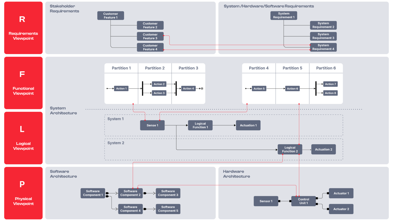
The RFLP methodology separates the problem space from the solution space. It ensures every engineering decision anchors to a specific requirement and translates accurately into physical implementations. Adopting this structured approach directly addresses the complexity of today's dynamic projects.
- Consistent Development: Drive innovation from initial stakeholder needs to final implementation.
- Clear Abstraction: Keep logical architectures distinct from physical hardware and modular software stacks.
- Built-in Quality: Integrate test specifications across all viewpoints to guarantee excellence.
Many teams struggle because their tools only support fragments of this process. PREEvision solves this exact challenge by offering full RFLP support in one environment.
The Vector Advantage. What Sets PREEvision Apart.
PREEvision translates the theoretical RFLP approach into a pragmatic, model-based reality. You eliminate data silos and establish a single source of truth for your entire engineering organization.
Horizontal and Vertical Traceability
Link requirements, functions, logical elements, and physical components seamlessly. Create, check, and navigate horizontal and vertical traceability links instantly with drag-and-drop simplicity.
Integrated Development Streams
Interact directly with requirements, test specifications, and system architectures in one environment. Avoid disruptive tool switches and maintain your engineering context.
Real-Time Collaboration and Transparency
Give all stakeholders access to up-to-date information at any time. Built-in ticketing links change requests directly to affected artifacts, ensuring complete transparency.
Model Integrity and Compliance
Rely on automated consistency checks and validation mechanisms to maintain model quality. PREEvision supports ASPICE and ISO 26262 standards natively.
Future-Proof Architectures
Scale your development for automotive, industrial, and medical domains. PREEvision supports agile workflows and adapts to the evolving challenges of modern systems engineering.
Systematic Reusability
Leverage proven architectures and components across multiple projects. PREEvision enables robust product line engineering, empowering you to manage system variants efficiently and accelerate the delivery of software-defined systems.
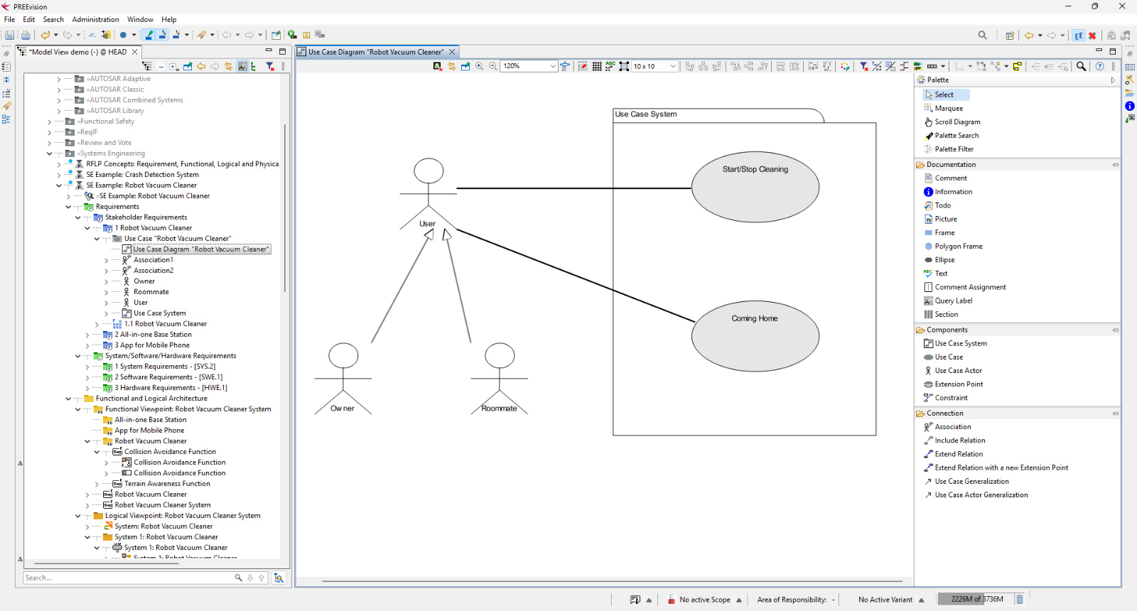
The Requirements Viewpoint
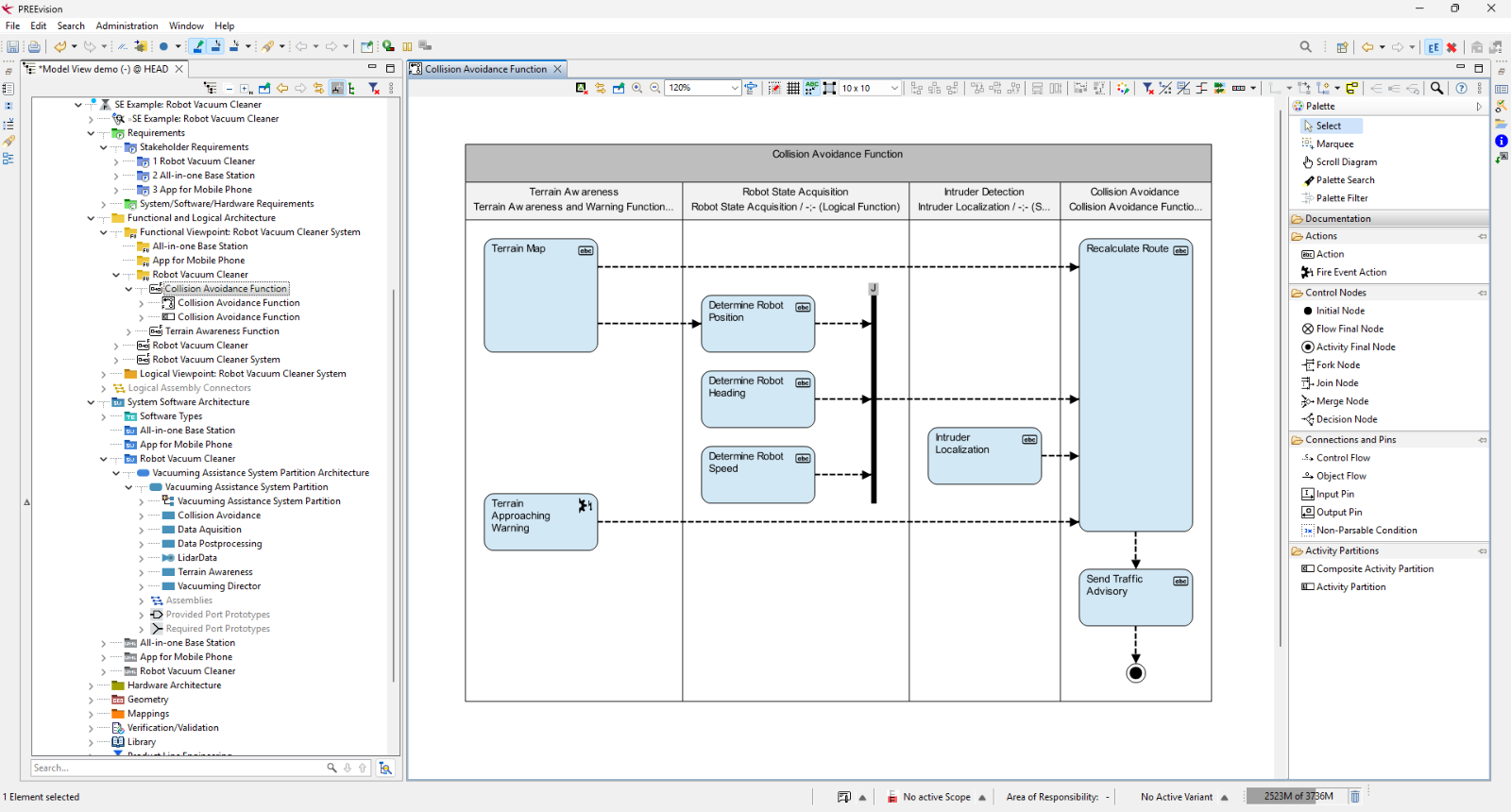
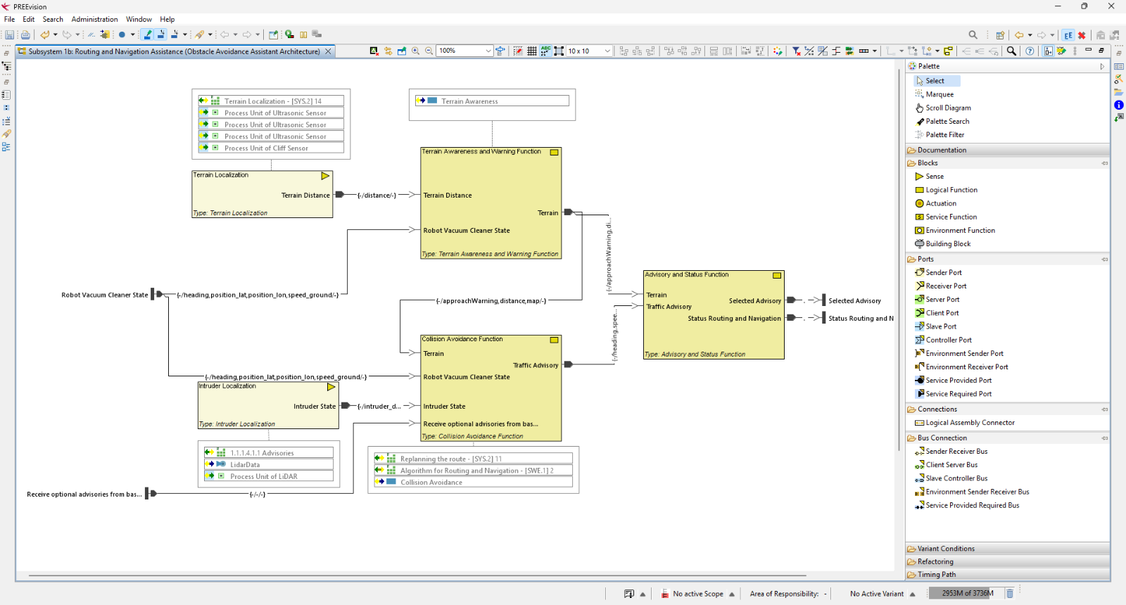
The Functional and Logical Viewpoint
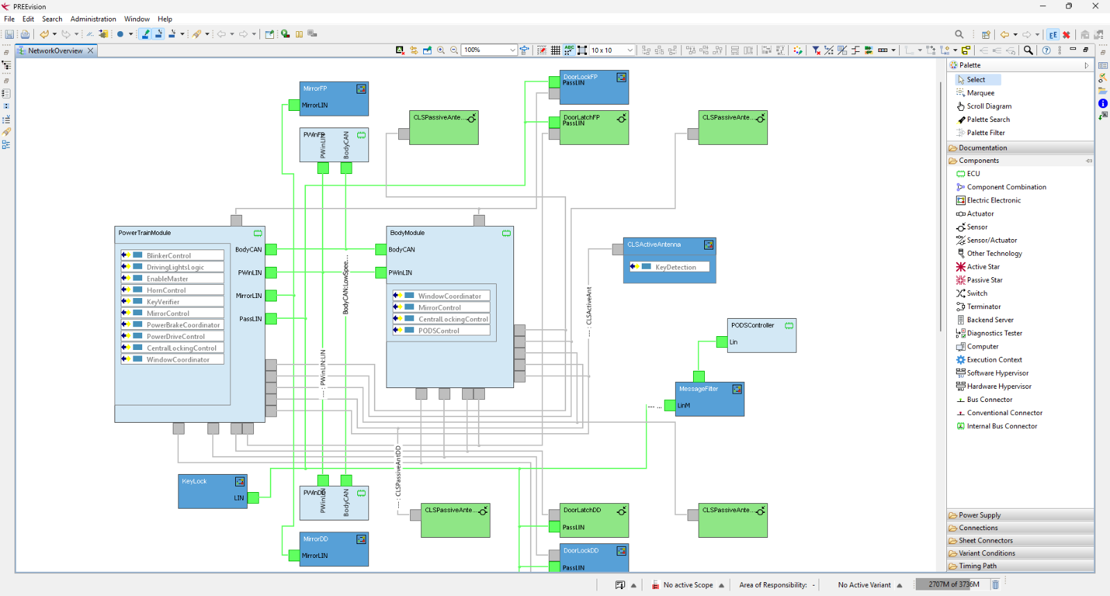
The Physical Viewpoint
Systems Engineering Beyond SysML

PREEvision delivers more than just SysML modeling. It acts as a comprehensive systems engineering platform that connects all development viewpoints.
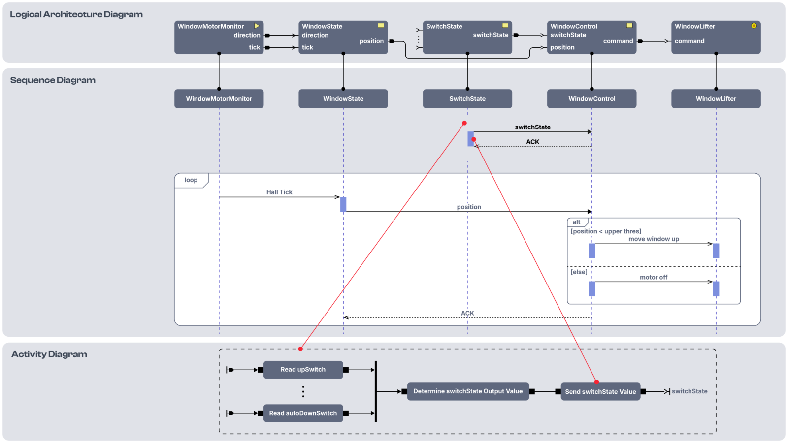
At its core, a unified data model enables bidirectional traceability across all abstraction layers – from requirements to architecture, hardware, software, testing, and workflow management.
Unified Modeling Across All Layers
From requirements capture to hardware and software integration, PREEvision connects every artifact through a centralized model. This setup boosts transparency, reduces rework, and keeps your teams focused on engineering tasks rather than tool complexity.
- Requirements Engineering: Capture stakeholder needs and trace them directly to system functions and components.
- Functional Architecture: Define system behavior and interactions using domain-specific views.
- Logical Design: Model logical components and ensure consistency with functional and physical layers.
- Physical Implementation: Map logical elements to real-world hardware and modular software stacks.
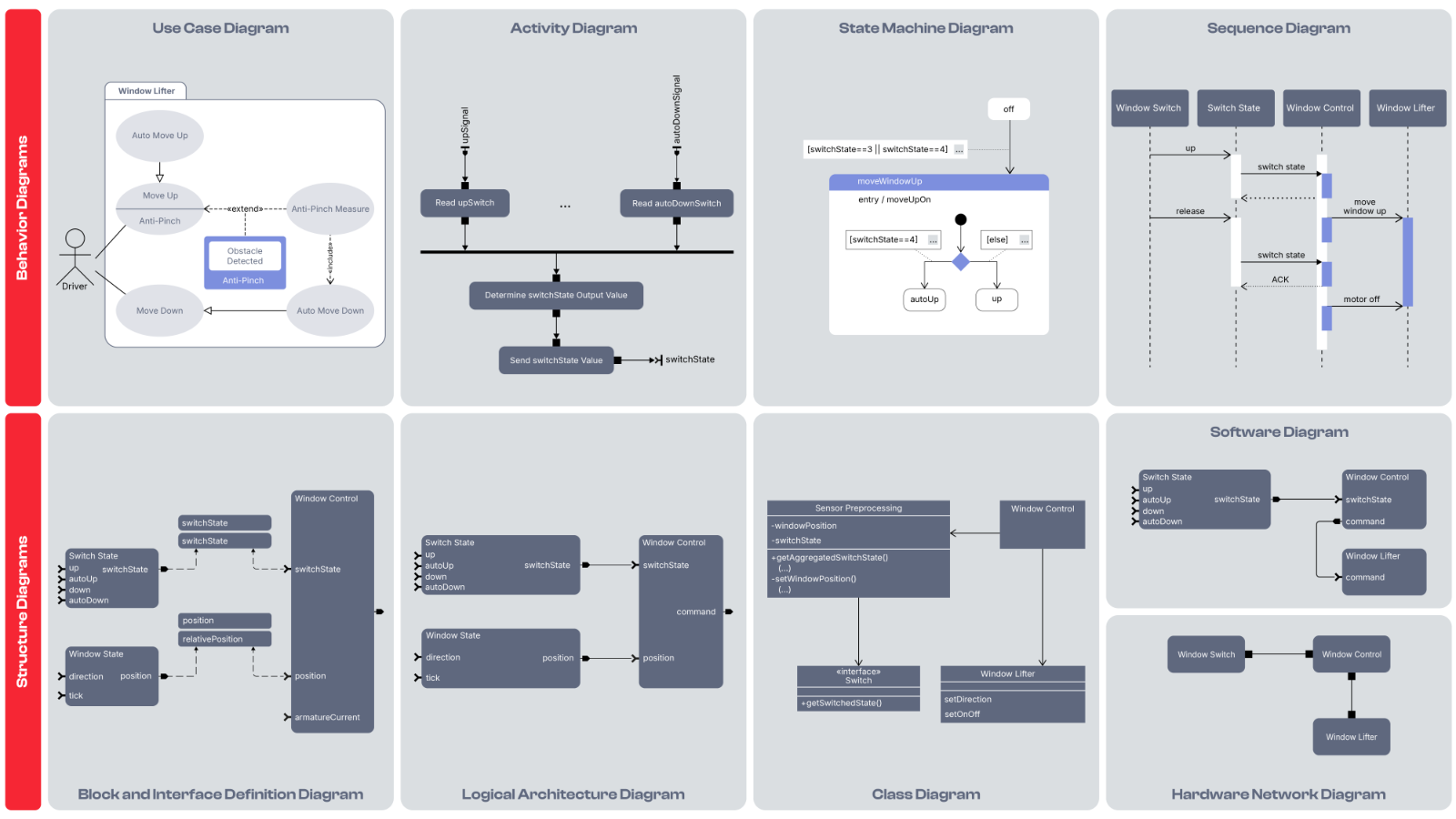
SysML-Based Diagrams in Action
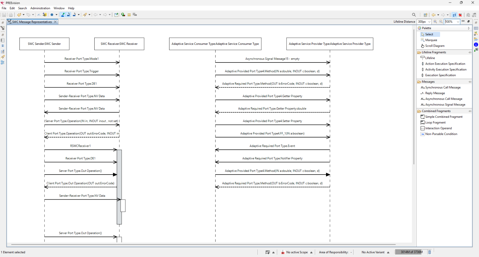
Leverage the Systems Modeling Language (SysML) directly within your RFLP workflows. PREEvision provides the standard notations you know, integrated seamlessly into the broader system model to visually structure and describe system design.
Behavior Diagrams
Visualize dynamic interactions using Use Case, Activity, State Machine, and Sequence Diagrams.
Structure Diagrams
Define static architectures with Block Definition, Logical Architecture, Class, and Hardware Network Diagrams.


Frequently Asked Questions
Explore More

MBSE in One Shared Platform
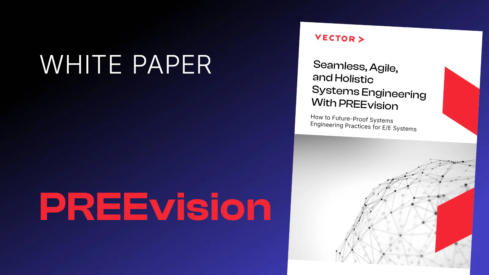
White Paper: MBSE With PREEvision